|
Kallio, Marke
VTT Processes, Hermiankatu 8 G, P.O.Box 16071, FI–33101 TAMPERE, Finland

VTT Publications 565, May 2005, 146 p.
[in English]
ISBN 951–38–6447–2
(soft back ed.)
ISBN 951–38–6639–4 (PDF edition)
Project: Säätyvät materiaalit
Keywords: magnetorheological elastomers, elastic properties, mechanical properties, viscoelastic properties, iron-carbonyl compounds,
stiffness damping properties, magnetic field strength, external load, particle network structure
Abstract
Magnetorheological elastomers (MREs) belong to the group of so-called smart materials, which respond to an external stimulus
by changing their viscoelastic properties. Magnetorheological (MR) material can be fluid, gel or solid material. The mechanical
properties of the MR materials change when subjected to an external magnetic field. The MREs are interesting candidates especially
for the active stiffness and vibration control of structural systems. The aim of this study was to increase the knowledge
on the mechanical and viscoelastic properties of isotropic and aligned MREs. The focus was to clarify the changes in the elastic
and vibration damping properties of both studied types of MREs when subjected to magnetic field. Isotropic and aligned MREs
were prepared from silicone elastomer matrix with varying carbonyl iron content. The MREs were tested in bending and compression
modes with sinusoidal dynamic loading. The 3-point bending experiments were carried out using a dynamic mechanical analyzer
(DMA) in resonance for both isotropic and aligned MREs where the filler content varied from 0 to 30 vol.%. For characterizing
the materials in compression with applied magnetic field, a special coil device was designed. Isotropic and aligned MREs with
30 vol.% of Fe were also characterized in dynamic compression with varying frequencies and strain amplitudes. The spring constant,
elastic/shear modulus and damping ratio/loss factor values were calculated on the basis of the measured data with and without
applied magnetic field. The results show, that the stiffness and damping properties of both isotropic and aligned MREs can
be modified by applying external magnetic field. The damping and stiffness properties of the MREs depend significantly on
the mutual directions of load, magnetic field and the particle alignment in the composite.
Contents
Abstract
Preface
List of symbols
1. Introduction
2. Magnetorheological fluids and foams
2.1 Physical properties of MR fluids
2.2 Field-responsive behavior of MR fluids
3. Magnetorheological elastomers (MRE)
3.1 MRE as a polymer composite
3.2 Models for predicting the mechanical properties of composites
3.3 Models for the field-responsive behavior of MR elastomers
4. Elastic properties and vibration damping of MREs
4.1 Influence of external magnetic field on the elastic properties of MREs
4.2 Influence of external magnetic field on vibration damping in MREs
4.3 Dynamic mechanical testing of MR elastomers
5. Preparation and process variables of MRE composites
5.1 Influence of the matrix material on the MRE behavior
5.2 Influence of particle size, shape and volume fraction on the behavior of MREs
5.3 Influence of particle magnetization on the behavior of MREs
6. Applications of MREs
7. Aim of the work
8. Experimental procedures
9. Preparation of the MRE composites
9.1 Starting materials
9.2 Preparation of MRE samples for dynamic mechanical testing
9.3 Preparation of MRE samples for compression testing
10. Dynamic and static measurements
10.1 Analysis of the dynamic systems
10.2 3-point bending tests
10.3 Compression testing
11. Results
11.1 Results of the DMA measurements
11.2 Results of the DMA measurements at elevated temperatures
11.3 Results of the static and dynamic compression testing
11.3.1 Static compression
11.3.2 Dynamic compression
12. Measurement of the elastic properties of the MREs
12.1 Ultrasonic measurements of the bulk modulus (K)
12.2 Elastic modulus values of isotropic MREs
12.3 Elastic modulus values of aligned MREs
13. Magnetization of the MREs
14. Discussion
14.1 Influence of particle arrangement on the properties of the studied MREs
14.2 Dynamic stiffness and moduli of the studied MREs
14.2.1 Isotropic MREs
14.2.2 Aligned MREs
14.3 Vibration damping properties of the studied MREs
14.3.1 Vibration damping of isotropic MREs
14.3.2 Vibration damping of aligned MREs
15. Conclusions
16. Proposal for future work
References
Figures and Tables
Table 1. Typical MR fluid properties [1, 3].
|
Property:
|
Typical value:
|
|
Maximum yield strength, ty (field)
|
50–100 MPa
|
|
Maximum field strength
|
~ 250 kAm-1 (0.3 Tesla)
|
|
Plastic viscosity, hp
|
0.1–1.0 Pas
|
|
Operable temperature range
|
-40°C to +150°C (limited by a carrier fluid)
|
|
Contaminants
|
Unaffected by most impurities
|
|
Response time
|
< milliseconds
|
|
Density
|
3–4 g/cm3
|
|
hp / ty2 (field), figure of merit*)
|
10-10–10-11 s/Pa
|
|
Maximum energy density
|
0.1 J/cm3
|
|
Power supply (typical)
|
2–25 V @ 1–2 A (2–50 watts)
|
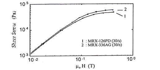
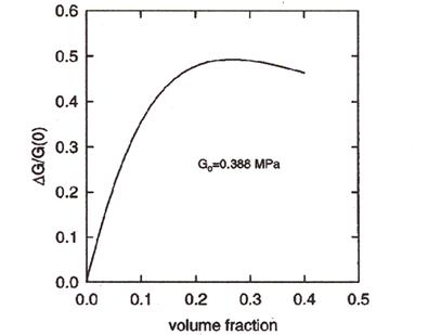
 Figure 1. Shear stress vs. applied magnetic field strength m0H for two commercial MR fluids [1].  Figure 2. Magnetic properties (flux density B vs. applied field strength μ0H) of two commercial MR fluids [1]. 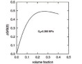 Figure 3. The predicted ratio of the change in modulus DG due to a strong magnetic field (B > 1 Tesla), where particle magnetization is saturated, to the zero-field modulus G(0)
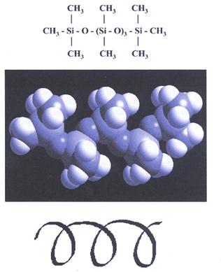
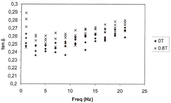
as a function of the volume fraction f of particles. The unfilled elastomer shear modulus G0 is 0.388 MPa [4]. 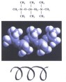 Figure 4. Helical structure of the polydimethylsiloxane backbone [17]. 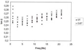 Figure 5. Loss factor (tan d ) of an isotropic MRE with 37.8 vol.% of iron as a function of the frequency, when measured without magnetic field and with
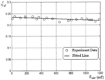
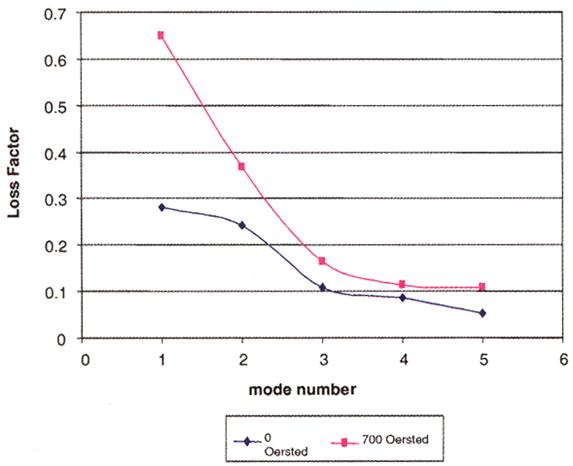
applied magnetic field strength of approximately 0.8 Tesla [7]. 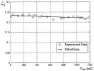 Figure 6. Damping ratio xd of the vibration system consisting of aligned silicone MRE with 27 vol.% of Fe as a function of the magnetic induction BMRE [10]. 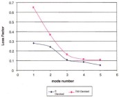 Figure 7. The loss factor values of different vibration modes measured for the sandwich beam structure consisting of an aligned
MRE layer with 30 vol.% of iron in between Al sheets, as measured in zero-field and with applied magnetic field strength of
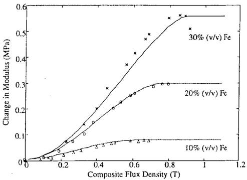
700 Oe (0.7 Tesla) [28].  Figure 8. Influence of the average magnetic flux density (magnetic induction) in the composite on the elastic modulus for
MR elastomers containing 10%, 20% and 30% of carbonyl iron by volume [1].
Table 2. The nominal modulus (no field applied) and the experimentally measured maximum change in modulus for MRE specimens
containing 10, 20 and 30 vol% of carbonyl iron as measured at 1.0% strain and at 2.0 Hz. The maximum change in the modulus
as predicted by the model of Jolly et al. [3] (assuming no gaps between particles) is also shown in the table.
|
Filler content in the test specimen:
|
Nominal modulus (MPa):
|
Max. change in modulus, experimental (MPa):
|
Max. change in modulus, model (MPa):
|
|
30 vol.% Fe
|
1.80
|
0.56 (31%)
|
0.55
|
|
20 vol.% Fe
|
0.74
|
0.29 (39%)
|
0.36
|
|
10 vol.% Fe
|
0.26
|
0.08 (30%)
|
0.17
|
Table 3. Some filler materials used in MR elastomers.
|
Filler particle type:
|
Composition and shape of the particles:
|
Particle size, average (mm):
|
Used in reference:
|
|
ISP-3700
|
Carbonyl iron, spherical
|
3
|
5, 10, 13
|
|
ISP R-2521
|
Carbonyl iron, spherical
|
5
|
2
|
|
BASF SQ
|
Carbonyl iron, spherical
|
3.9–5.0
|
6
|
|
BASF EW
|
Carbonyl iron, spherical
|
3.5, 13, 23
|
14
|
|
BASF HQ
|
Carbonyl iron, spherical
|
2
|
9
|
|
Höganäs ASC100.29
|
Pure iron, irregular
|
< 180
|
6
|
|
Höganäs AT40.29
|
Pure iron, irregular
|
200
|
6
|
|
Höganäs ASC300
|
Pure iron, irregular
|
< 60
|
6
|
Table 4. The calculated CPVC values for MR elastomers with different iron fillers.
|
Filler particle type:
|
Apparent density (g/cm3):
|
Critical particle volume concentration (vol.%):
|
Reference:
|
|
ISP-3700
|
1.9 (1.5–3.0)
|
24.1
|
ISP (analysis)
|
|
BASF SQ
|
2.3
|
29.1
|
BASF (analysis)
|
|
Höganäs ASC300
|
2.88
|
36.5
|
6
|
|
Höganäs ASC100.29
|
2.98
|
37.7
|
6
|
|
Höganäs AT40.29
|
3.02
|
38.2
|
6
|
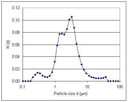
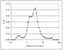 Figure 9. Particle size distribution of the carbonyl iron ISP-3700 powder used in the present work as measured by the Lecotrac
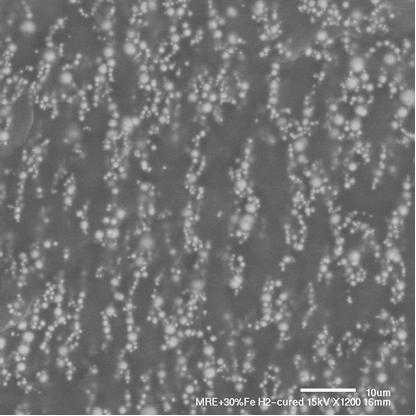
LT-100 laser particle size analyzer. 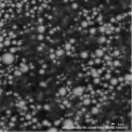 Figure 10. Microstructure of an isotropic MRE with 30 vol.% of Fe. A BEI mode SEM image taken from the freeze-fractured surface.
Magnification 2000´. 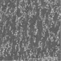 Figure 11. Microstructure of an aligned MRE with 30 vol.% of Fe. A BEI mode SEM image taken from the freeze-fractured surface.
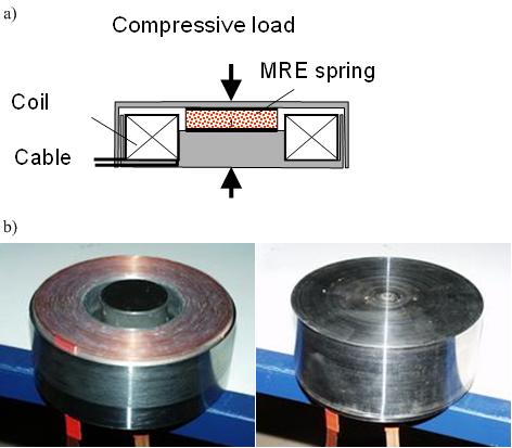
Magnification 1100´.  Figure 12. The idealized dynamic system with single degree of freedom and the equilibrium of forces. The symbols are: displacement
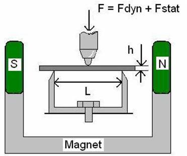
z, spring constant k, viscous damping constant b and the mass of the system m. The forces acting in the system are: applied load F(t), inertia force Fi, damping force Fd and the elastic spring force Fs. 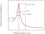 Figure 13. Frequency-response curve of a moderately damped system. For the definition of the symbols see the text. 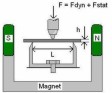 Figure 14. 3-point bending DMA measurement system for rectangular samples with the permanent magnet. L (5 mm) is the distance
between the supports and h (1.6 mm) the height of the sample. The width of the sample was varied from 3 to 5 mm and the distance
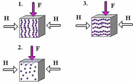
between the poles and the sample was varied from 2 mm to 3 mm. 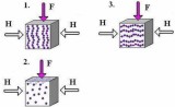 Figure 15. Measuring directions of aligned MREs in the DMA measurements. Oscillating force is 1. parallel to the chains, 2.
and 3. perpendicular to the chains. In the Direction 2. the magnetic field direction is perpendicular and in the Direction
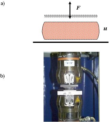
3. parallel to the particle chains. 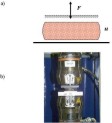 Figure 16. a) Schematic presentation of the MRE spring element, b) the testing apparatus with the sample inserted. 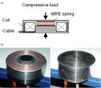 Figure 17. (a) Schematic presentation of the magnetic coil device with MRE (b) MRE spring element inside the magnetic coil
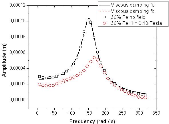
device with the top cover open (left) and closed (right). 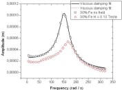 Figure 18. DMA frequency scan results for an isotropic MRE with 30 vol.% of iron. The results are shown with fitted viscoelastic model and they were measured without the magnetic field and with
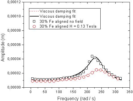
the field strength H of 0.13 Tesla.  Figure 19. DMA frequency scan results of an aligned MRE with 30 vol.% of iron as measured in Direction 1 (see Fig. 15). The
results are shown with fitted viscoelastic model, and they were measured without the magnetic field (upper curve) and with
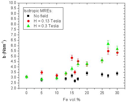
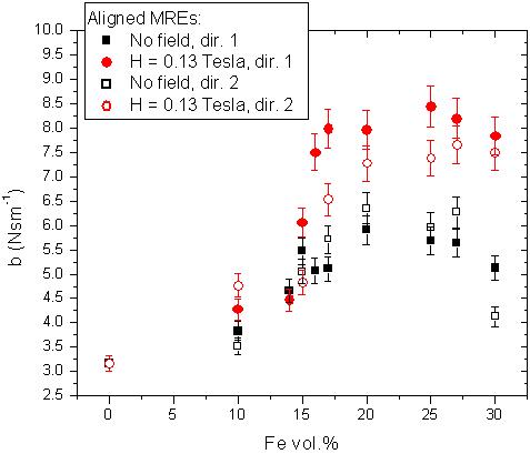
the field strength H of 0.13 Tesla (lower curve). 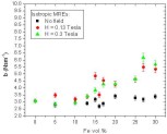 Figure 20. Measured average viscous damping constant b of isotropic MREs as a function of the filler content. The damping
constant was measured both without magnetic field and with the field strength H values of 0.13 and 0.3 Tesla. 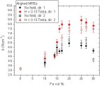 Figure 21. Average viscous damping constant b of aligned MREs versus the filler content as measured in Directions 1 and 2 (see Fig. 15). The damping constant is measured
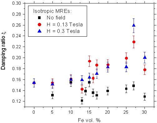
both without the magnetic field and with the field strength H of 0.13 Tesla. 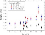 Figure 22. Calculated average viscous damping ratio x of isotropic MREs as a function of the filler content. The damping ratio is measured both without the magnetic field and
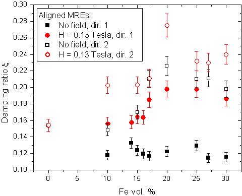
with the field strength values of 0.13 and 0.3 Tesla. 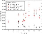 Figure 23. Calculated average viscous damping ratio x of aligned MREs as a function of the filler content, when measured in Directions 1 and 2 (see Fig. 15). The damping ratio
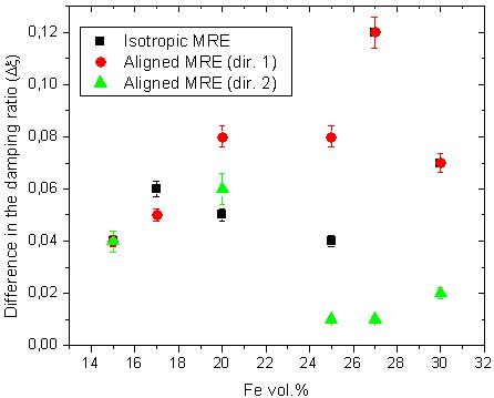
is measured both without the magnetic field and with the field strength H of 0.13 Tesla. 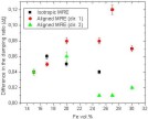 Figure 24. Difference in the damping ratio (Dx) between the passively measured values and the values measured with the magnetic field strength of 0.13 Tesla for both isotropic
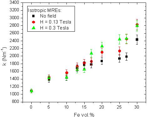
MREs and aligned MREs measured in Directions 1 and 2 (see Fig. 15). 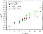 Figure 25. Measured average spring constant k of isotropic MREs as a function of filler fraction. The spring constant is measured both without the magnetic field and with
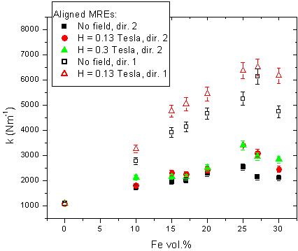
the field strength H values of 0.13 and 0.3 Tesla. 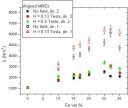 Figure 26. Average spring constant k of aligned MREs as a function of the filler content when measured in Directions 1 and 2 (see Fig. 15). The spring constant
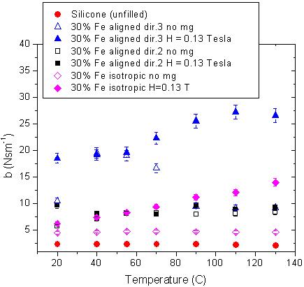
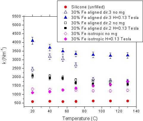
is measured both without the magnetic field and with the field strength H values of 0.13 and 0.3 Tesla in Direction 2. 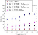 Figure 27. Damping constant b as a function of temperature as measured for both isotropic and aligned MREs with 30 vol.% of Fe in Directions 2 and 3 (see
Fig. 15) and for the unfilled elastomer M4601. The MREs are measured passively and with the magnetic field strength of 0.13
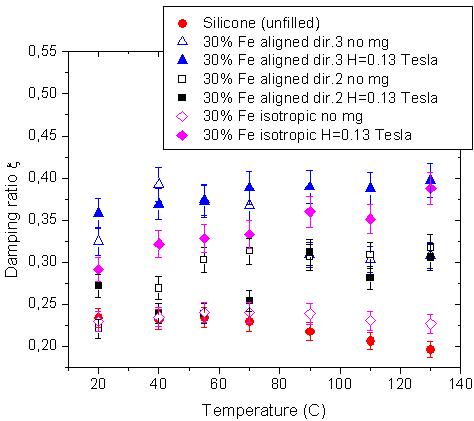
Tesla. 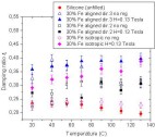 Figure 28. Damping ratio x as a function of temperature measured for isotropic and aligned MRE with 30 vol.% of Fe in Directions 2 and 3 (see Fig. 15)
and for unfilled elastomer M4601. The MREs are measured both passively and with magnetic field strength of 0.13 Tesla. 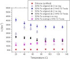 Figure 29. Spring constant k as a function of temperature measured for both isotropic and aligned MREs with 30 vol.% of Fe in Directions 2 and 3 (see
Fig. 15) and for unfilled elastomer M4601. The MREs are measured both passively and with the magnetic field strength of 0.13
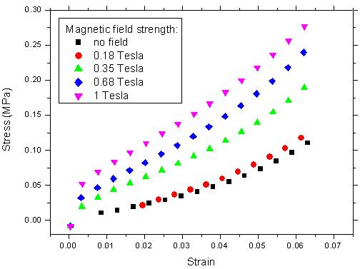
Tesla. 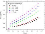 Figure 30. Stress-strain curves measured in compression with Coil device 2 at room temperature for the aligned MRE with 30
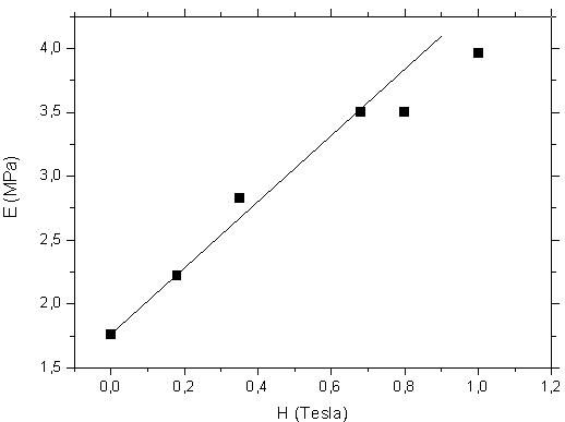
vol.% of Fe in the direction of chains and with different magnetic field strength values.  Figure 31. Room temperature elastic modulus E of an aligned MRE with 30 vol.% of Fe as a function of magnetic field strength H. The modulus is measured and the magnetic field is applied in the direction
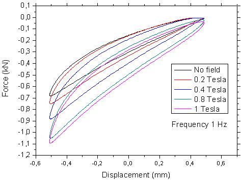
of chains. 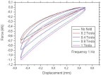 Figure 32. Measured force-displacement loops with different magnetic field strength values for the aligned MRE with 30 vol.%
of Fe, when studied with the applied load and magnetic field in the direction of chains in Coil device 2 with testing frequency
of 1 Hz.
Table 5. Average changes (in %) of the spring constant and loss factor values of an aligned MRE as measured in the direction
of chains at different frequencies, when the magnetic field strength H is increased from 0 to 0.35 Tesla in Coil 1. The isotropic
MRE is measured at 10 Hz with H = 0.35 Tesla.
|
Material
|
Aligned
MRE 30%
|
Isotropic
MRE 30%
|
|
Frequency (Hz)
|
0.5
|
1
|
5
|
10
|
15
|
10
|
|
Increase in spring constant (%)
|
10.0
|
11.2
|
11.4
|
11.2
|
12.2
|
11.0
|
|
Increase in loss factor (%)
|
30.6
|
30.5
|
16.6
|
8.0
|
13.3
|
11.7
|
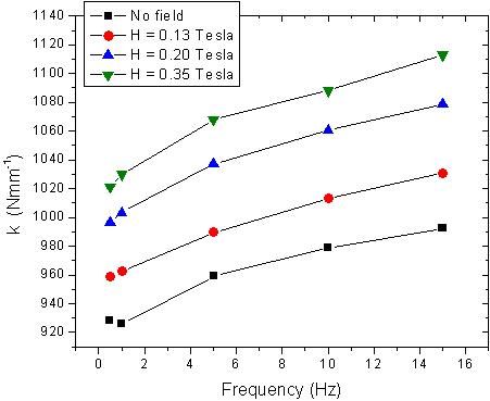
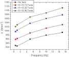 Figure 33. Spring constant k of an aligned MRE with 30 vol.% Fe as a function of the testing frequency, when measured in the direction of chains with
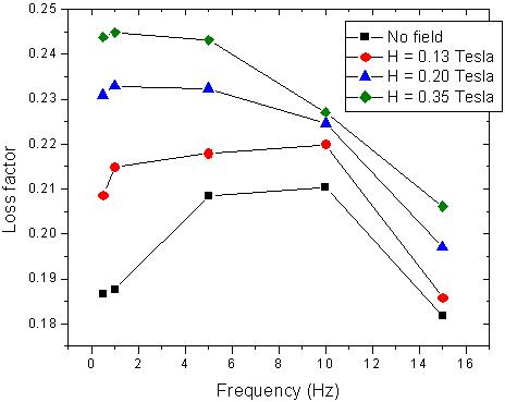
different magnetic field strength values in Coil 1. The magnetic field is applied in the direction of chains. 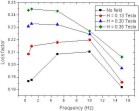 Figure 34. Loss factor of an aligned MRE with 30 vol.% Fe as a function of the testing frequency, when measured in the direction
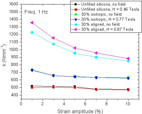
of chains with different magnetic field strength values in Coil 1. The magnetic field is applied in the direction of chains. 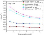 Figure 35. Spring constant k of an unfilled silicone (M4644) as well as of the isotropic and aligned MREs with 30 vol.% of Fe as a function of the strain
amplitude when measured in Coil 1 both without and with the magnetic field using the frequency of 1 Hz. The magnetic field
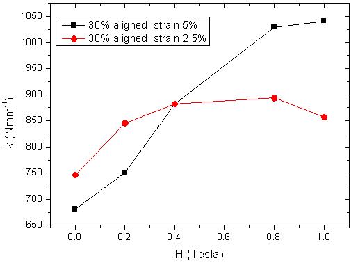
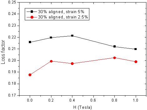
is applied in the chain direction. 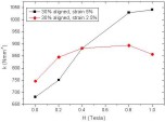 Figure 36. Spring constant k of the aligned MRE with 30 vol.% Fe when measured as a function of the magnetic field strength H inside Coil 2, at the frequency of 1 Hz with 2.5% and 5% compressive strain amplitudes. 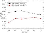 Figure 37. Loss factor of aligned MRE with 30 vol.% of Fe as a function of the magnetic field strength H, when measured in Coil 2 at the
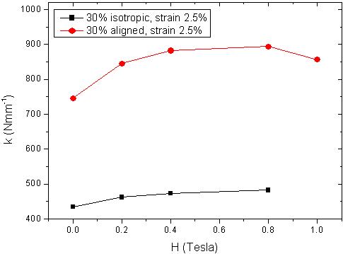
frequency of 1 Hz with 2.5% and 5% compressive strain amplitudes. The magnetic field is applied in the direction of chains. 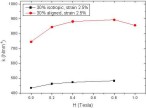 Figure 38. Comparison of the spring constant k of isotropic and aligned MREs with 30 vol.% of Fe as a function of the magnetic field strength when measured at the frequency
of 1 Hz and with the strain amplitude of 2.5% in Coil 2. The magnetic field is applied in the direction of chains. 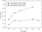 Figure 39. Comparison of the loss factor values of isotropic and aligned MREs with 30 vol.% of Fe as a function of the magnetic field strength
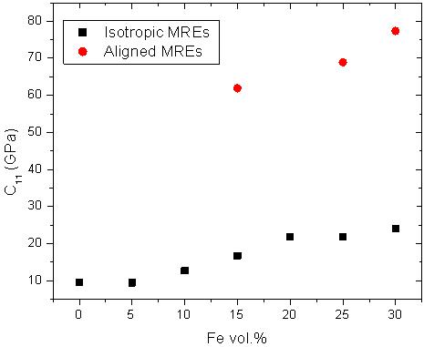
when measured at the frequency of 1 Hz and with the strain amplitude of 2.5% in Coil 2. The magnetic field is applied in the direction of chains. 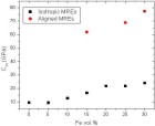 Figure 40. Longitudinal modulus c11 of isotropic and aligned MREs as a function of filler content when measured without the magnetic field.
Table 6. The material parameters used in the calculation of shear moduli values with the non-dilute model of Christensen [19].
|
Shear modulus of the inclusions
|
80 GPa
|
|
Shear modulus of the matrix
|
0.004 GPa
|
|
Bulk modulus of the inclusions
|
200 GPa
|
|
Bulk modulus of the matrix
|
9 GPa
|
|
Poisson’s ratio of the inclusions
|
0.35
|
|
Poisson’s ratio of the matrix
|
0.5
|
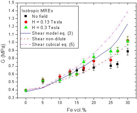
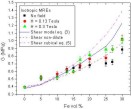 Figure 42. Calculated values of the shear modulus G of isotropic MREs as a function of filler content when the DMA measurements were carried out both without external magnetic
field and with the magnetic field strength H values of 0.13 and 0.3 Tesla. Experimental results are compared to the values
predicted by Equation (3) and to the values suggested by the non-dilute and concentrated suspension models (Eq. (5)) by Christensen
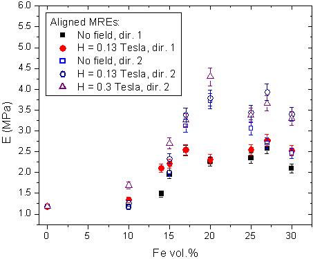
[19].  Figure 43. Young’s modulus E of aligned MREs as a function of the filler content when measured in Directions 1 and 2 (see Fig. 15) both without the magnetic
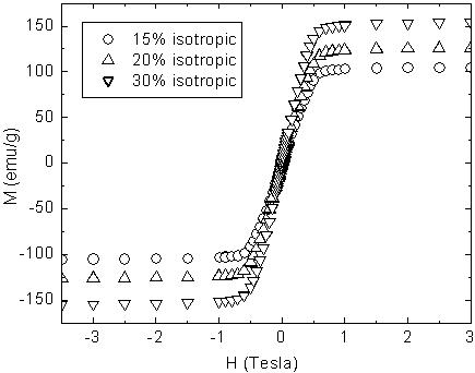
field and with the field strength H values of 0.13 and 0.3 Tesla. 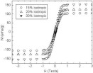 Figure 44. Magnetization curves measured with the SQUID for the isotropic MREs with 15, 20 and 30 vol.% of Fe.
References
[1] Carlson, J.D. & Jolly, M.R. 2000. MR fluid, foam and elastomer devices. Mechatronics 10, pp. 555–569.
[2] Watson, J.R. 1997. U.S. Patent 5609353, EP0784163 Ford Motor Co, GB.
[3] Jolly, M.R., Carlson, J.D. & Munoz, B.C. 1996. A model of the behaviour of magnetorheological materials. Smart Mater. Struct.
5, pp. 607–614.
[4] Davis, L.C. 1999. Model of magnetorheological elastomers. J. Applied Phys., Vol. 85, No. 6, pp. 3348–3351.
[5] Ginder, J.M., Clark, S.M., Schlotter, W.F. & Nichols, M.E. 2002. Magnetostrictive phenomena in magnetorheological elastomers.
Int. J. Modern Phys. B, Vol. 16, Nos. 17&18, pp. 2412–2418.
[6] Lokander, M. & Stenberg, B. 2003. Performance of isotropic magneto–rheological rubber materials. Polymer Testing 22, pp. 245–251.
[7] Lokander, M. & Stenberg, B. 2003. Improving the magnetorheological effect in isotropic magnetorheological rubber materials.
Polymer Testing 22, pp. 677–680.
[8] Ray, S., Shanmugharaj, M. & Bhowmick, K. 2002. A new parameter for interpretation of polymer-filler and filler-filler interactions
in rubber vulcanizates. J. Mater. Sci. Letters 21, pp. 1097–1100.
[9] Bellan, C. & Bossis, G. 2002. Field dependence of viscoelastic properties of MR elastomers. Int. J. Modern Phys. B, Vol. 16,
Nos. 17&18, pp. 2447–2453.
[10] Zhou, G.Y. 2003. Shear properties of a magnetorheological elastomer. Smart Mater. Struct. 12, pp. 139–146.
[11]
Horvath, A.T., Klingenberg, D.J. & Shkel, Y.M. 2002. Determination of rheological and magnetic properties for magnetorheological
composites via shear magnetization measurements. Int. J. Modern Phys. B, Vol. 16, Nos. 17&18, pp. 2690–2696.
[12] Zhou, G.Y & Li, J.R. 2003. Dynamic behavior of a magnetorheological elastomer under uniaxial deformation: I. Experiment. Smart
Mater. Struct. 12, pp. 859–872.
[13] Ginder, J.M., Schlotter, W.F. & Nichols, M.E. 2001. Magnetorheological elastomers in tunable vibration absorbers. Smart Structures and Materials 2001: Damping and Isolation.
Inman, D.J (Ed.). Proceedings of SPIE, Vol. 4331. Pp. 103–110.
[14] Demchuk, S.A. & Kuzmin, V.A. 2002. Viscoelastic properties of magneto-rheological elastomers in the regime of dynamic deformation.
Journal of Engineering Physics and Thermophysics, Vol. 75, No. 2, pp. 396–400.
[15] Li, W.H., Du, H., Chen, G. & Yeo, S.H. 2001. Viscoelastic properties of MR fluids under oscillatory shear. Smart Structures and Materials 2001: Damping and Isolation.
Inman, D.J. (Ed.). Proceedings of SPIE, Vol. 4331. Pp. 333–342.
[16] Wacker Silicones, Material safety data sheet. 2003. Elastosil M4644 A, M4644 B.
[17] de Buyl, F. 2001. Silicone sealants and structural adhesives. International Journal of Adhesion & Adhesives 21, pp. 411–422.
[18] Ferry, J.D. 1980. Viscoelastic properties of polymers. John Wiley & Sons, Inc.
[19] Christensen, R.M. 1979. Mechanics of composite materials. John Wiley & Sons, Inc.
[20] Weaver, W. Jr., Timoshenko, S.P. & Young, D.H. 1974. Vibration problems in engineering. John Wiley & Sons, Inc.
[21] Schreiber, E., Anderson, O.L. & Soga, N. 1973. Elastic constants and their measurement. McGraw-Hill, Inc.
[22] Molnar, L. & Huba, A. 2001. Measurement of dynamic properties of silicone rubbers. Periodika Polytechnica Ser. Mech. Eng.,
Vol. 45, No. 1. pp. 87–94.
[23] Daughton, D.R., MacDonald, J. & Mulders, N. 2003. Acoustic properties of silica aerogels between 400 mK and 400 K. J. Non-Crystalline
Solids 319, pp. 297–303.
[24] Glough, R. & Penzien, J. 1975. Dynamics of structures. McGraw-Hill, Inc.
[25] Borcea, L. & Bruno, O. 2001. On the magneto-elastic properties of elastomer-ferromagnet composites. J. Mechanics and Physics of Solids 49 pp. 2877–2919.
[26] Shiga, T., Okada, A. & Kurauchi, T. 1995. Magnetroviscoelastic behavior of composite gels. J. Applied Polymer Science, Vol.
58, pp. 787–792.
[27] Shen, Y., Golnaraghi, M.F. & Heppler, G.R. 2004. Experimental research and modeling of magnetorheological elastomers. J. Intelligent
Material Systems and Structures, Vol. 15, pp. 27–35.
[28] Yalcintas, M. & Dai, H. 2004. Vibration suppression capabilities of magnetorheological materials based adaptive structures.
Smart Mater. Struct. 13, pp. 1–11.
[29] Jiles, D. 1994. Introduction to magnetism and magnetic materials. Chapman & Hall.
[30] Zhou, G.Y. & Jiang, Z.J. 2004. Deformation in magnetorheological elastomer and elastomer-ferromagnet composite driven by a
magnetic field. Smart Mater. Struct. 13, pp. 309–316.
[31] Dorfmann, A. & Ogden, R.W. 2003. Magnetoelastic modeling of elastomers. European Journal of Mechanics A/ Solids 22, pp. 497–507.
[32] Guth, E. 1945. Theory of filler reinforcement. J. Appl. Physics 16, pp. 20–25.
[33] Leblanc, J.L. 2002. Rubber-filler interactions and rheological properties in filled compounds. Prog. Polym. Sci. 27, pp. 627–687.
[34] Payne, A.R. & Whittaker, R.E. 1971. Low strain dynamic properties of filled rubbers. Rubber Chem. Tech. 44, pp. 440–478.
[35] Ginder, J.M. & Davis, L.C. 1994. Shear stresses in magnetorheological fluids: Role of magnetic saturation. Appl. Phys. Lett. 65 (26), pp. 3410–3412.
[36] Yin, H.M., Sun, L.Z. & Chen, J.S. 2002. Micromechanics-based hyperelastic constitutive modeling of magnetostrictive particle-filled
elastomers. Mechanics of Materials 34, pp. 505–516.
[37] Lemaire, E., Meunier, A. & Bossis, G. 1995. Influence of the particle size on the rheology of magnetorheological fluids. J. Rheol. 39 (5), pp. 1011–1020.
[38] Bossis, G., Lacis, S., Meunier, A. & Volkova, O. 2002. Magnetorheological fluids. J. Magnetism and Magnetic Materials 252, pp. 224–228.
[39] Farshad, M. & Benine, A. 2004. Magnetoactive elastomer composites. Polymer Testing 23, pp. 347–353.
[40] Ginder, J.M., Nichols, M.E., Elie, L.D. & Tardiff, J.L. 1999. Magnetorheological elastomers: properties and applications. SPIE – The International Society for Optical Engineering. Proceedings
of the 1999 Smart Structures and Materials on Smart Materials Technologies, Mar 3 – Mar 4, Newport Beach, CA, USA 1999. Vol.
3675. Pp. 131–138.
[41] Ginder, J.M., Nichols, M.E., Elie, L.D. & Clark, S.M. 2000. Controllable-stiffness components based on magnetorheological
elastomers. Smart Structures and Materials 2000: Smart Structures and Integrated Systems. Wereley, N.M. (Ed.). Proc. of SPIE,
Vol. 3985. Pp. 418–425.
[42] Radcliffe, C.J., Lloyd, J.R., Andersland, R.M. & Hargrove, J.B. 1996. State feedback control of electrorheological fluids.
1996 ASME Congress and Exhibition, November 17–22, Atlanta, GA.
[43] Courtney, T.H. 1990. Mechanical behavior of materials. McGraw-Hill Publishing Company.
[44] Wang, M.-J. 1998. Effect of polymer-filler and filler-filler interactions on dynamic properties of filled vulcanizates. Rubber
Chemistry and Technology, Vol. 71, pp. 520–559.
[45] Zhou, G.Y. 2004. Complex shear modulus of a magnetorheological elastomer. Smart Mater. Struct. 13, pp. 1203–1210.
[46] Jolly, M.R., Carlson, J.D., Munoz, B.C. & Bullions, T.A. 1996. The magnetoviscoelastic response of elastomers composites consisting
of ferrous particles embedded in a polymer matrix. J. Intelligent Mater. Systems and Structures, Vol. 7, pp. 613–622.
[47] McKnight, G. & Carman, G.P. 1999. Energy Absorption and Damping in Magnetostrictive Composites. Materials Research Symposium,
Smart Materials, Boston Dec.
|